To measure VSWR (Voltage Standing Wave Ratio) using Davicom products such as the BPS1050 or BPS5095 RF Power Sensors, follow these steps:
System Set Up
1- Connect the transmitter end of the BPS to your transmitter.
2- Attach the antenna end of the BPS to either an inline power meter (to verify power output) or directly to the load if the transmitter power is already known.
3- Connect the forward power and reflected power voltage terminals of the BPS to separate metering inputs on your Davicom RTU.
Metering Inputs Configuration Using the Web Interface
Configure the metering inputs for Forward Power and Reflected Power through the RTU’s web interface:
1- Open a web browser and connect to the Davicom RTU’s web interface using its IP address.
2- Navigate to Inputs > Metering Inputs.
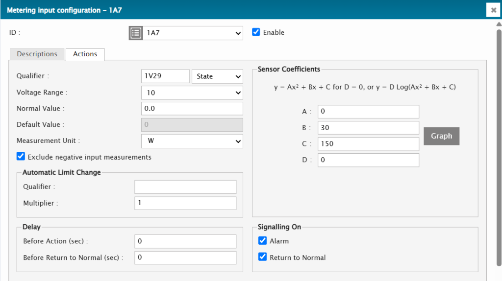
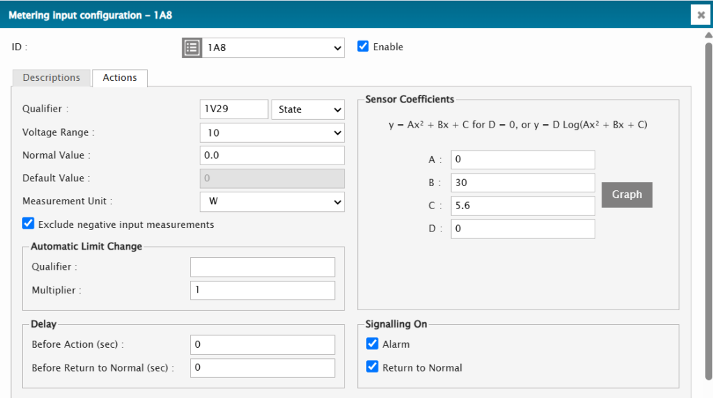
3- For each metering input:
- Select the input connected to the Forward Power terminal of the BPS.
- Configure the following parameters:
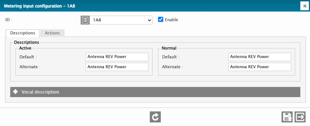
- Description: Forward Power
- Measurement Unit: Watts (or as applicable)
- Normal Value: Enter the typical forward power value for your setup.
- Calibration Coefficients: Input the specific coefficients (A, B, C) from the BPS documentation based on the operational frequency:
- BPS1050 at 170 MHz: A = 8.9053, B = 4.4987, C = 0
- BPS5095 at 870 MHz: A = 4.5311, B = 3.0904, C = 0
- Repeat this process for the metering input connected to the Reflected Power terminal, adjusting the description accordingly.

BPS Calibration
Accurate calibration ensures the Davicom RTU’s forward power reading matches the actual transmitter output:
1- Use a Reference Meter: Set up an inline power meter between the BPS and the load to act as your reference.
2- Turn On the Transmitter: Power up the transmitter and stabilize its output.
3- Adjust the Calibration Trimmer:
- Locate the forward voltage calibration trimmer on the BPS sensor.
- Using a small insulated screwdriver, gently adjust the trimmer while monitoring the forward power reading on the Davicom RTU.
- Continue adjusting until the forward power reading displayed by the Davicom RTU matches the reference value shown on the inline power meter.
Automatic VSWR Calculation Configuration
Once the metering inputs are calibrated, you can set up automatic VSWR calculation:
1- Navigate to Inputs > Math Functions in the RTU’s web interface.
2- Choose an available math function slot.
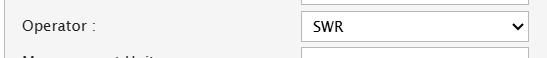
3- In the Operator dropdown menu, select the SWR function.
4- In the fields provided for the SWR operator:
- Field A (Reflected Power): Enter the ID for the metering input connected to the reflected power terminal of the BPS.
For example, if Reflected Power is connected to Metering Input 8, the ID will typically be 1A8. - Field B (Forward Power): Enter the ID for the metering input connected to the forward power terminal of the BPS.
For example, if Forward Power is connected to Metering Input 7, the ID will typically be 1A7.

5- Assign a description to the math function, such as “VSWR Calculation.”
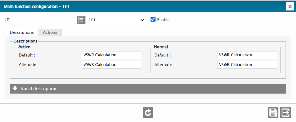
6- Save the settings to activate the VSWR calculation.

Displaying VSWR Reading
1- Navigate to the monitoring panel in the web interface.
2- Add the configured math function to a dashboard or display panel for real-time VSWR monitoring.
